Ladder Physics, Part 1
This post answers a question my dad asked me. It turns out this is literally a textbook physics problem, but it was fun to think through.
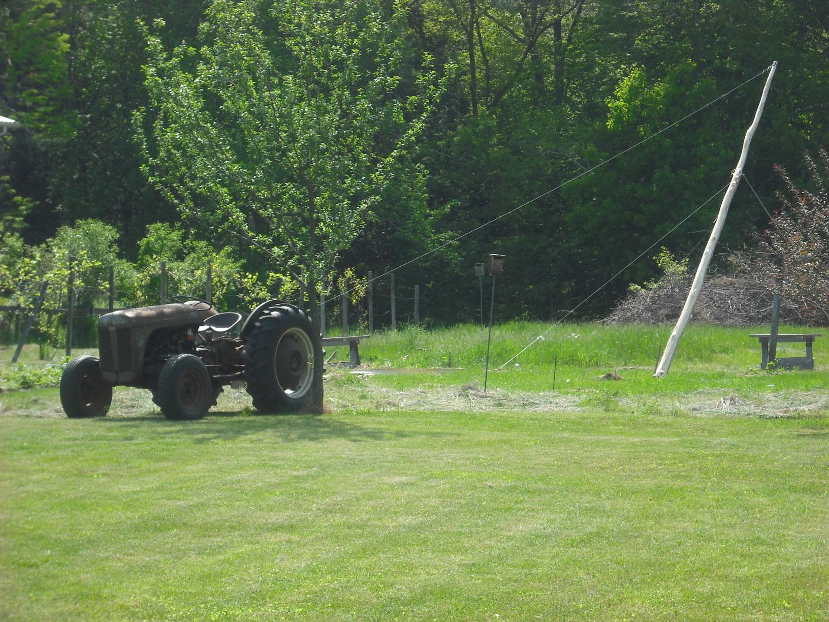
My dad grows hops in his backyard on this great trellis system that’s basically a 22’ limbed skinny tree trunk supported by several guy wires:
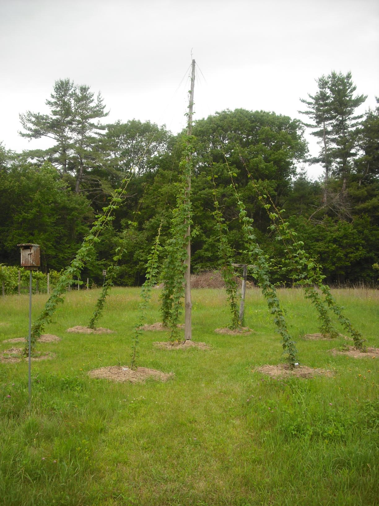
To trim/harvest/maintain, he leans an extension ladder against the central pole. Understandably, he worries a bit about the load on the pole from the ladder.
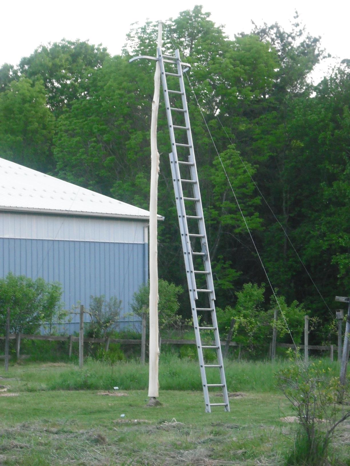
So the question is, how does the load on the pole change with the angle and the center of mass of the ladder? He said that he tries to stand the ladder as close to vertical as he’s comfortable with because his feeling was that if the ladder was steeper then the horizontal load would be less. When you first think about this, it feels a little complicated: gravity is pushing down, the ground is pushing back up, friction keeps the ladder from sliding… so why is there a load on the pole at all?
Problem setup
This really comes down to static force balance. Let’s start with a sketch of the situation to define a few things:
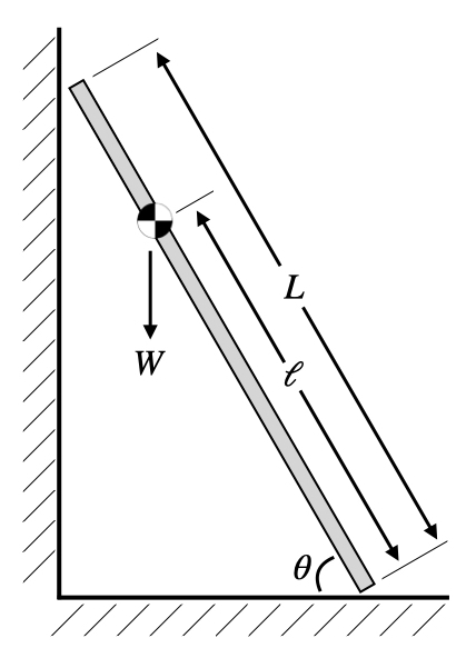
Here $L$ is the total length of the ladder and $\theta$ is the angle between the ladder and the ground. To keep things simple I just drew in the center of mass of the ladder and its distance $\ell$ from the base. In other words $W$ is the combined weight of my dad and the ladder. Calculating $\ell$ from the mass of the ladder, the mass of my dad, and where he is on the ladder is fairly straightforward, but we can come back to that. Using the center of mass simplifies things because we can just act as if all the weight of the combined dad/ladder system is acting on that point.
To find the load on the pole as a function of $\theta$, we start by assuming (hoping?) that the ladder is not moving. In order for that to be true, we need two conditions to hold:
- The sum of forces acting on the ladder is zero in all directions
- The sum of torques acting on any point is zero for all axes
In this 2D planar model we have two components of net force and one torque axis.
Besides the weight, there are a couple of other forces at play. At both ends of the ladder the fixed surfaces exert a “normal” force on the ladder. These normal forces come up whenever an object is resting on a solid surface and they represent the net result of all the molecular forces holding the surface together and preventing the object from falling through it. For instance, if the ladder was lying flat on the ground, then the normal force from the ground would have to be $W$ in the “up” direction in order for the net force to be zero. The normal forces always act perpendicular to the surfaces, and their magnitudes will have to be determined from force/torque balance.
There’s also the force of friction from the ground that prevents the ladder from sliding. An easy way to think about this is that the ladder is “pinned” in place, so there is also some yet-to-be-determined horizontal force acting on the ladder from the “pin” (which is really the static friction from the ground). There’s also friction from the wall, but I think intuition says that this is not going to be nearly as significant as the friction required to keep the ladder from sliding horizontally.
Let’s call the normal force from the wall/pole $N_w$, from the ground $N_g$, and the friction/pin force $F_g$. Now we can draw a free-body diagram like this:
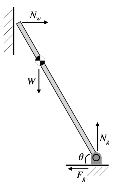
Note that according to Newton’s third law, the wall normal force $N_w$ acting on the ladder is really a “reaction force” against some equal and opposite force from the ladder acting on the wall. This is the load we want to calculate.
Force/torque balance
The next step is to calculate the force balance conditions. First, in the vertical direction, \begin{equation} N_g = W. \end{equation}
In other words, the normal force from the ground balances the full weight, just as if the ladder was lying flat on the ground. This would be a bit different if we accounted for wall friction, since that would also act vertically and balance some of the weight.
Force balance in the horizontal direction is \begin{equation} N_w = F_g. \end{equation}
So the magnitude of the load on the wall is actually exactly the same as the friction force from the ground. In order to actually find out what that force is, we have one more step: torque balance.
In three dimensions, torque calculations have to be done with a vector cross product, but planar torques are easier, since the torque axis is always perpendicular to the plane of the forces. For a force $F$ acting at an angle $\varphi$ to a lever arm of length $r$, the torque is $\tau = r F \sin \varphi$.
The $rF$ term in this equation simply says that if you push harder or use a longer lever arm, you get more torque. And a force acting on a point produces zero torque at that point. Recognizing that $\sin \varphi$ is zero at zero degrees and reaches a maximum at 90 degrees, this term is also fairly intuitive: if you’re turning a wrench you get the most torque by pushing perpendicular to the handle of the wrench (and no torque at all if you pull or push along the handle!). Finally, whether the torque points “into” or “out of” the plane is determined with the right-hand rule.
Back to the ladder problem. We have to pick any point about which we can calculate the torques. We might as well choose the “pivot” in the free-body diagram, where the ladder meets the ground. Then since $N_g$ and $F_g$ both act through that point they produce no torque there and we only have torque from $W$ and $F_w$. The weight acts through the center of mass at a distance $\ell$, and is at an angle of $90^\circ - \theta$ to the ladder. Since $\sin (90^\circ - \theta) = \cos \theta$, the torque from the weight is $\ell W \cos \theta$. The normal force from the wall is at a distance $L$ and at an angle of $\theta$, so the torque is $L F_w \sin \theta$. The right-hand rule tells us that the weight-torque is positive, and the wall-torque is negative, so torque balance is \begin{equation} \ell W \cos \theta = L N_w \sin \theta. \end{equation}
Rearranging a bit, and using the trig identity $\cos \theta / \sin \theta = \cot \theta$, the normal force from the wall (again, equal and opposite to the load on the wall) is \begin{equation} N_w = \frac{\ell W}{L} \cot \theta. \end{equation}
Before putting any numbers in, let’s analyze this a little bit. This is what the cotangent function looks like:
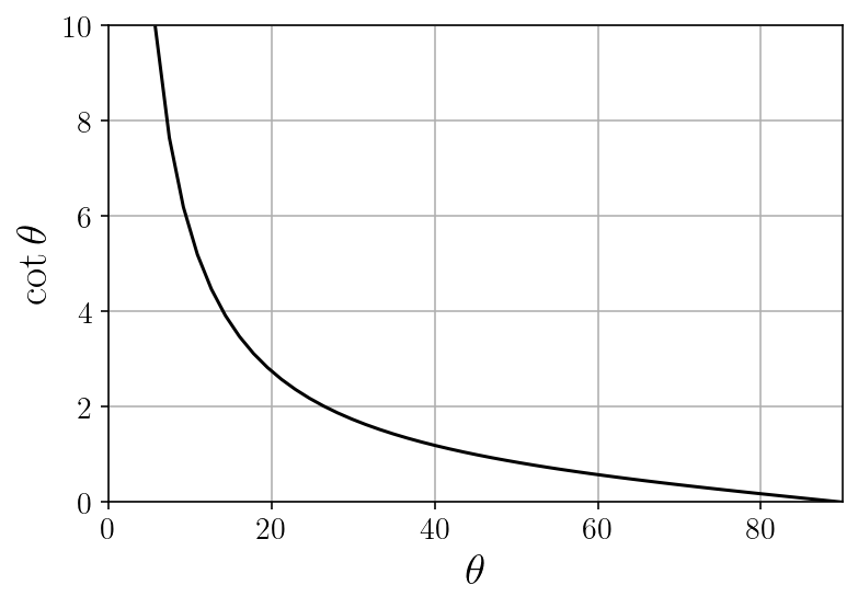
So for any weight and center of mass location, the force on the wall goes to zero as $\theta$ goes to $90^\circ$, just like my dad’s intuition said. What might be a little more surprising is that the force goes to infinity as $\theta$ goes to $0^\circ$. I definitely didn’t see the ladder this way to begin with, but I think the easiest way to understand this is to look at the ladder as a second-class lever with the fulcrum at the base. As the ladder gets closer and closer to the ground, the wall has worse and worse leverage since the normal force is acting more and more parallel to the lever arm. Conversely, as you descend the ladder and $\ell / L$ decreases, the center of mass moves towards the “fulcrum” and the ladder has better leverage, so $N_w$ decreases.
Also, since the static friction force from the ground is also equal in magnitude to the load on the wall, this also has the intuitive practical implication that the shallower the angle of the ladder is, the more likely it is to slip backwards on the ground. In other words, load on the wall is an equivalent concern to sliding stability.
To put some numbers on this, my 24’ extension ladder is about 35 lbs, and I weigh about 160. If the mass of the ladder is more or less uniformly distributed, its center of mass is 12’ up. If my center of mass was 2’ from the top of the ladder, the approximate center of mass of the combined system could be calculated with the weighted average \begin{equation} \ell = \frac{12 * 35 + 22 * 160} {35 + 160} \approx 20.2’. \end{equation}
[Side note:] I’m admittedly being sloppy with mass/weight units here because I’m talking about backyard projects which in the US happen in Imperial units. There should be a few gravitational acceleration constants that factor out in order to convert lbs to whatever the Imperial unit of mass is.
In this case the load on the pole would look like this:
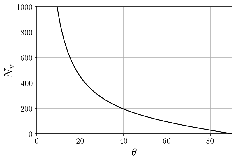
Fortunately, even at a pretty comfortable $60^\circ$, the load on the pole is still only around 100 lbs. This is also the region where $\cot \theta$ is approximately linear, so as a first approximation you can think about the load increasing about linearly up to about this point.
Load on the guy wires
So far we have computed the normal force on the ladder from a fixed wall in order to have force/torque balance in the ladder. And, by Newton’s third law, this is equivalent to the load on our pole from the ladder. But in this situation, the ladder isn’t quite leaning against a fixed wall. The pole itself is another free body that is supported by the guy wires. As a simple model of this, we could next look at the tension in a single wire directly aligned with the ladder, which corresponds to the maximum possible tension on any one wire in the 3D situation.
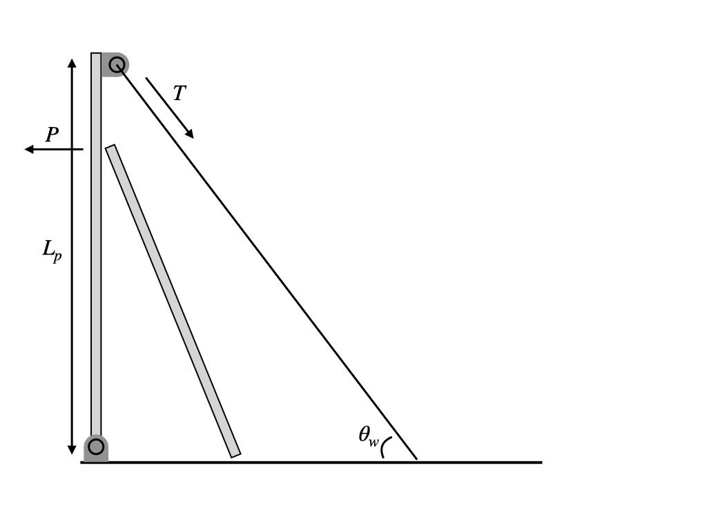
This diagram includes the ladder just for visual orientation, but remember that now we’re looking at a free-body diagram for the pole, so we don’t need to think about any forces on the ladder. Since we already determined the load $P = N_w$, we could just ignore the ladder altogether and treat it as a load concentrated at a single point.
To be complete, we should technically also add the force of friction due to the ladder ($F_w$ above), the normal force from the ground, and the weight of the pole. However, this is really another torque balance problem: what does the tension in the wire need to be in order to balance the load from the ladder and have zero resultant torque about the bottom of the pole? Since the ladder friction, normal force on the pole, and weight of the pole are all directed along the “lever arm” of the pole, they exert no torque and we can ignore them.
With a little geometry, the torque balance about the bottom point of the ladder is \begin{equation} P L \cos \theta = T L_p \cos \theta_w \end{equation}
Both sides of the equation calculate the torque $\tau = rF \sin \varphi$ as described above. On the left-hand side the load $P$ is acting perpendicular to the pole (so $\sin \varphi = 1$), but at a distance $r = L \cos \theta$ from the base. On the right-hand side, the tension $T$ has as its lever arm the full length of the pole $L_p$, but now $\sin \varphi = \sin(90^\circ - \theta_w) = \cos \theta_w$ since the force is not perpendiculer to the lever arm.
Solving for the tension and using $P = \ell W \cos \theta / L \sin \theta$ from the ladder calculation, \begin{equation} T = \frac{L_p \cos \theta_w \tan \theta}{\ell W \cos \theta} \end{equation}
Here’s the tension using the same ladder parameters as above, plus $L_p = 22’$ and $\theta_w = 60^\circ$:

Now the tension looks like it explodes towards the lower end of the graph, although keep in mind this represents angles you’d never actually set a ladder at. And again, this model assumes that the ladder will never slip on the ground, so you couldn’t even if you wanted to. The second plot shows a more realistic range of ladder positions, for which the tension doesn’t exceed 50 lbs.
Bending moment in the pole
There’s one more thing we might worry about here: what about the bending moment in the pole? This is a relatively skinny tree trunk that now sits out in the weather all day, so you might well worry about it snapping where the ladder is sitting aginst it. First of all, you probably shouldn’t trust a simple physics model over an instinct that says “Hey, this wood feels a little rotten.” That said, here’s a simple physics model.
If we consider the pole as a simple beam with two supports and a load somewhere in between, we can use a standard result in mechanics: three-point bending in an Euler-Bernoulli beam:
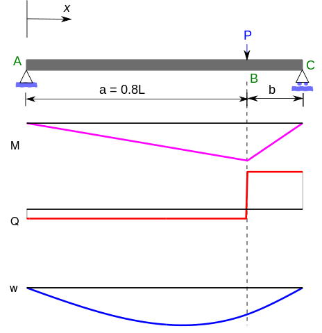
I’m not going to derive this result here, but it turns out the maximum bending moment in that beam is $M = P a b / L$. In our notation, the beam length $L$ is the pole length $L_p$, $a = L \sin \theta$, and $b = L_p - L \sin \theta$. After a little algebra, the maximum bending moment in the pole is \begin{equation} M = \ell W \cos \theta \left( 1 - \frac{L}{L_p} \sin \theta \right) \end{equation}
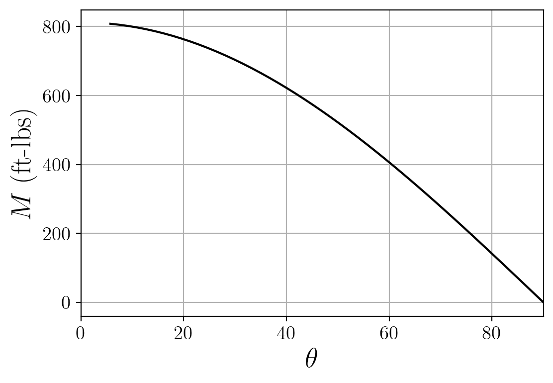
Granted, the y-axis in the plot doesn’t mean all that much. The outcome of applying this bending moment to the pole will depend on the material properties of the pole, and as I said, I’m not going to speculate on those here. But I think the interesting thing is that the blow-up of the load and tension as $\theta \rightarrow 0$ doesn’t happen in this case, since the load gets closer and closer to the fixed support at the base. Though again, the small-angle regime isn’t really of any practical relevance for ladders.
Summary
With a little back-of-the-envelope modeling of the ladder as a second-class lever, it looks like my dad’s intuition held up pretty well. You’re better off having the ladder be as vertical as possible to avoid loading the pole/wire, and placing the top of the ladder as close to the top of the pole as possible reduces the bending moment in the pole. In principle, the pole only needs to support something like 100 lbs, and the guy wires need to handle around 50 lbs of tension. On paper it looks okay! Which I’m sure is what OSHA loves to hear.
As with a lot of these types of problems, I think the main trick is just setting up the free-body diagram properly. But this is an interesting “back to basics” type of problem, and I was surprised to rethink the ladder as a lever. Next time I’ll take a totally different approach to the same problem using Lagrangian mechanics.